Following on from post 1 and post 2 on this project.
On Monday we met to discuss the latest prototypes of the Filter Box and the Pressure Box.
Filter box:
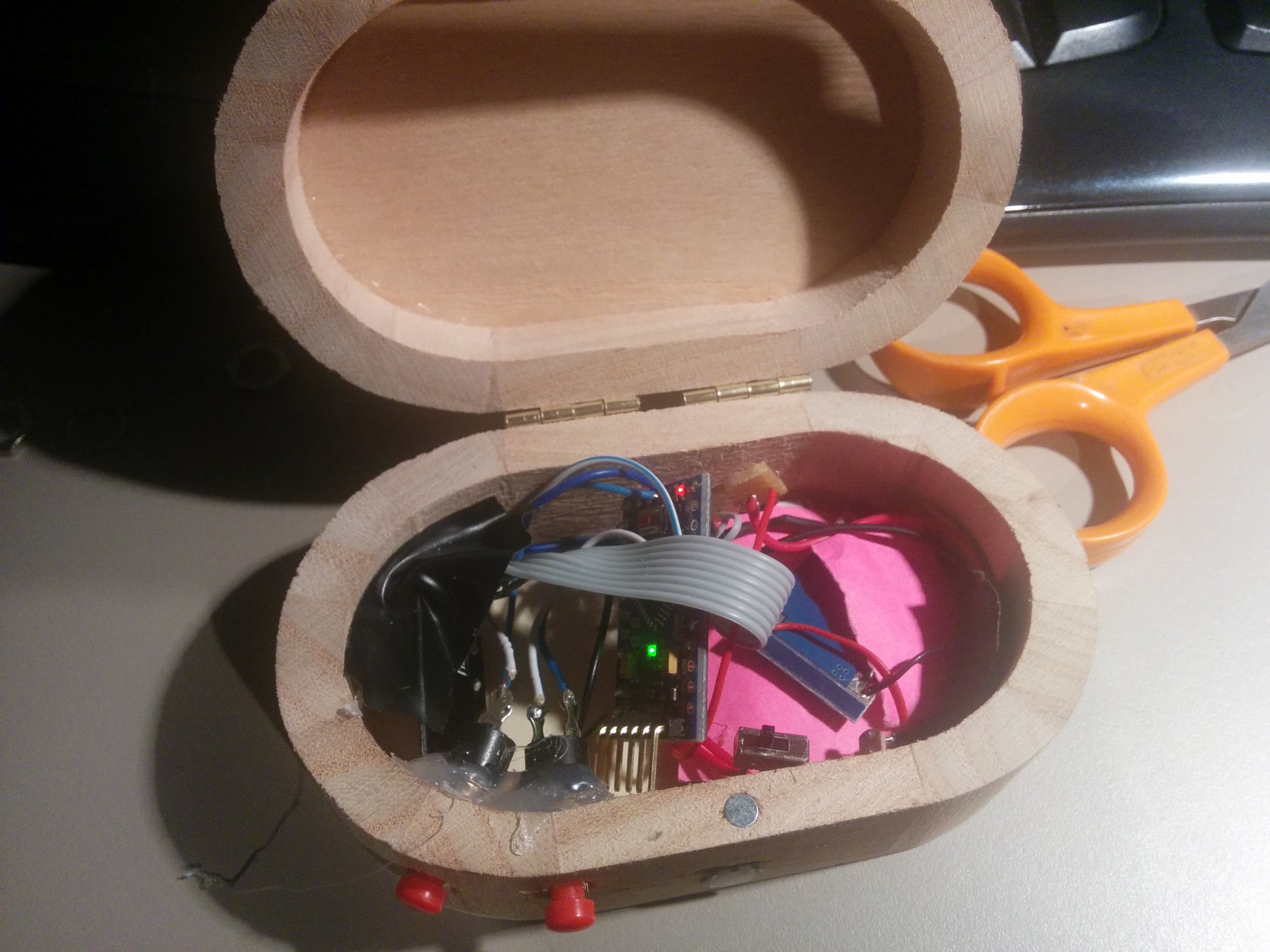
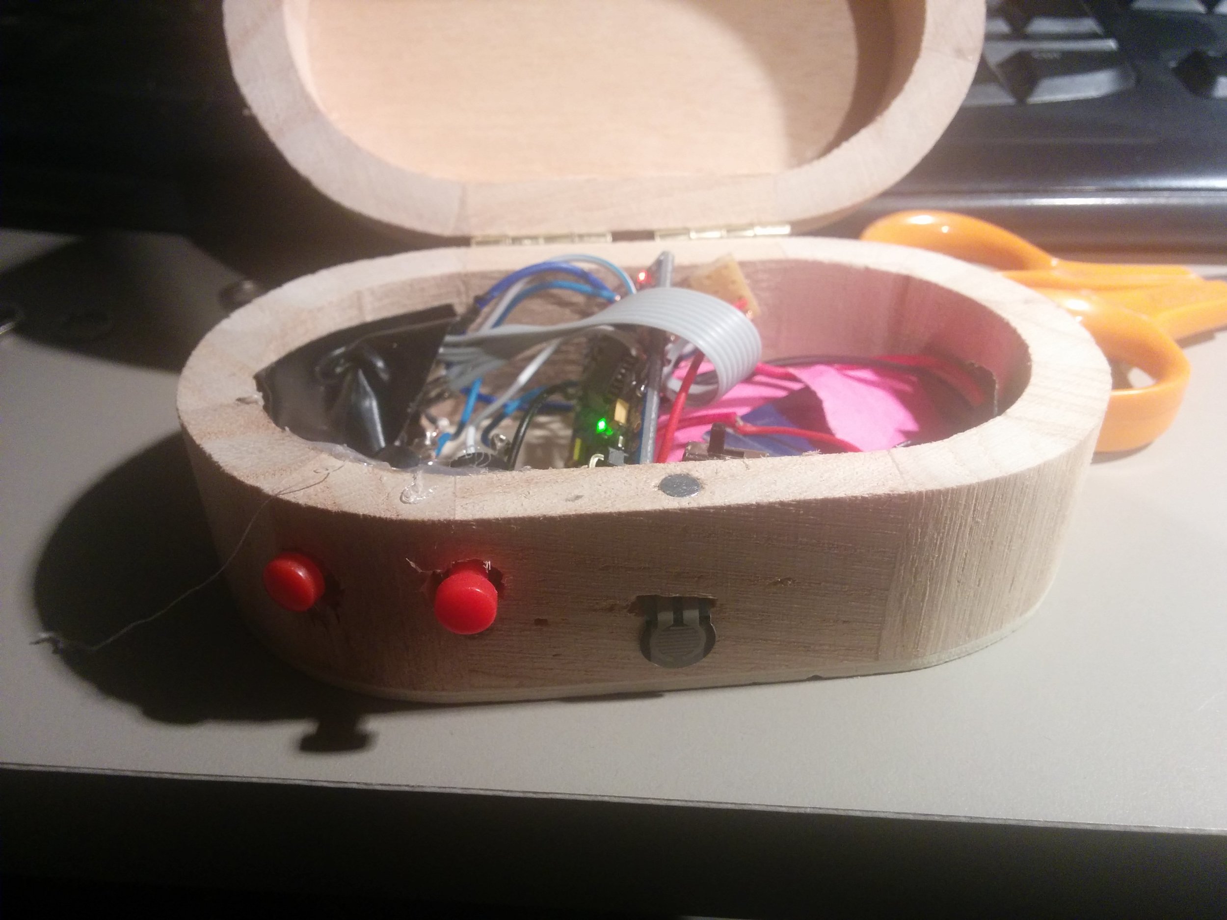
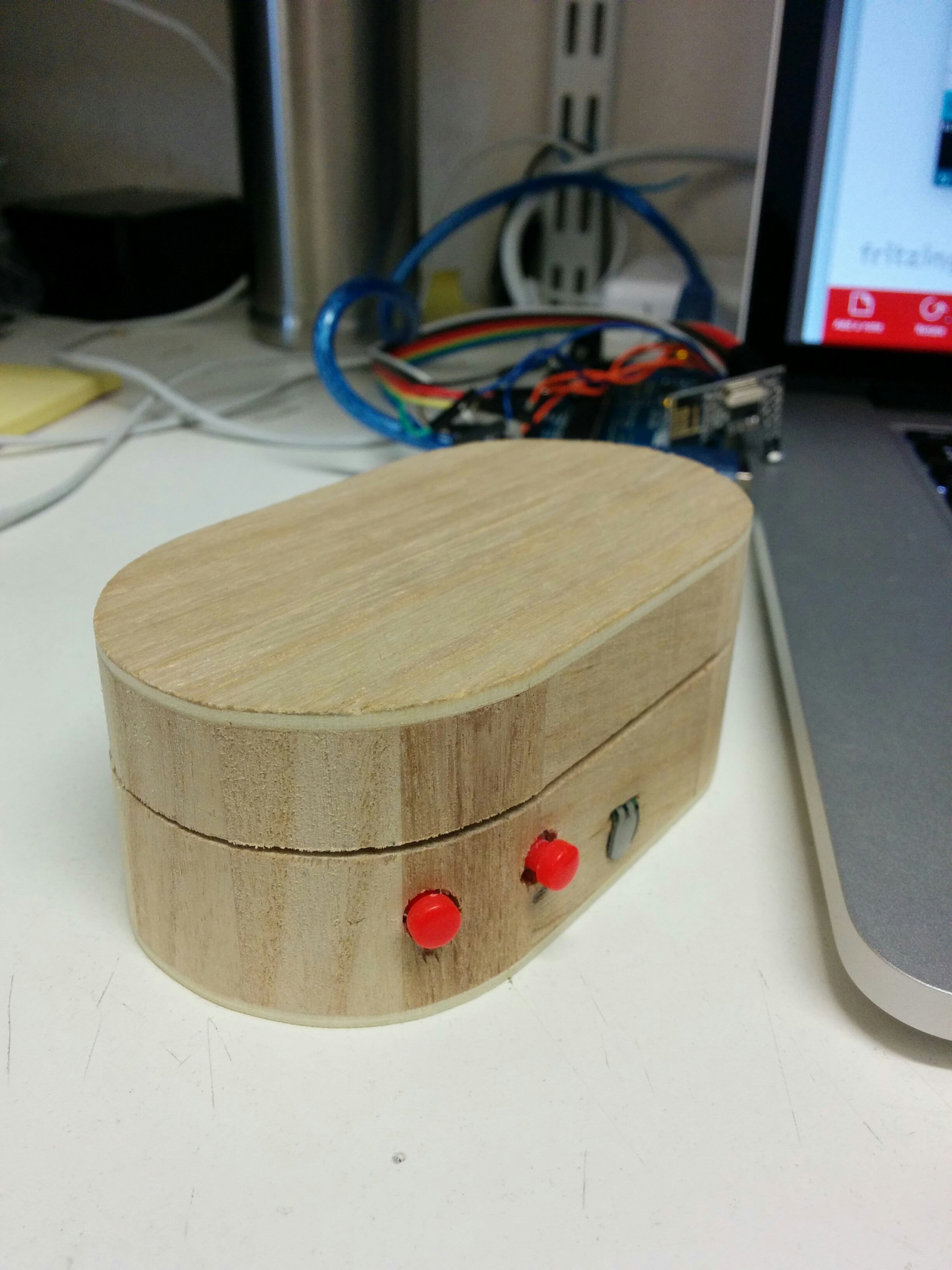
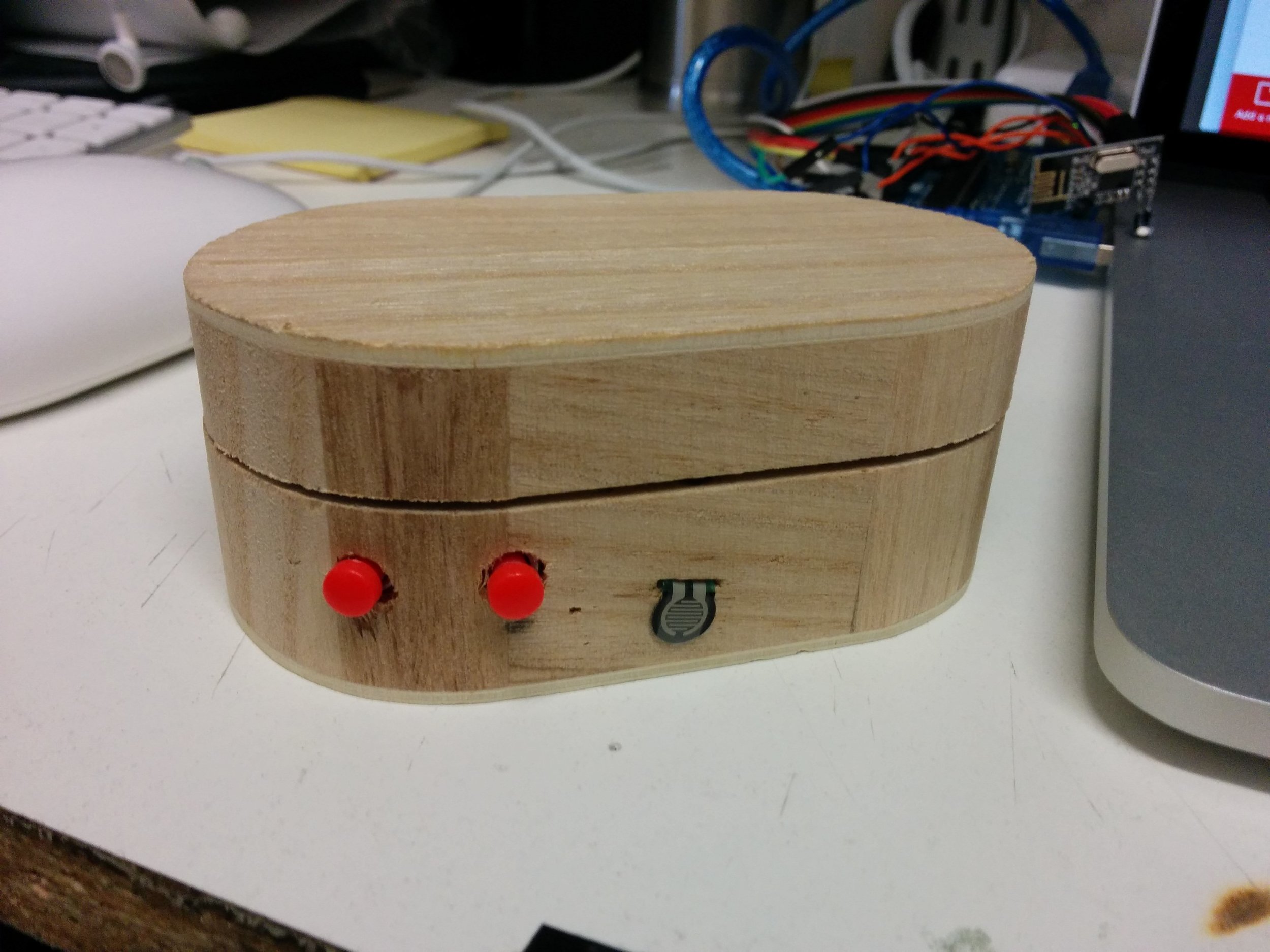
We had selected the small oval box as the one most suitable for the Filter Box and I set to work adding 2 valve style buttons and 1 force sensitive resistor to go alongside the light dependent resistor already installed in the prototype.
Parts added to existing prototype:
1 x Force sensitive resistor (FSR)
Circuit:

A note on the resistors for the buttons; no resistors are needed on the buttons if you enable the inbuilt resistors in the Arduino, you can do this in the code uploaded to the board. We did not use resistors on the buttons and so the code below will mean that the buttons are considered to be high or on until pressed which will then turn the input to low or off. So these buttons send a 1 when not being pressed and a 0 when pressed.
The Code:
https://github.com/lwoodbury/AMI
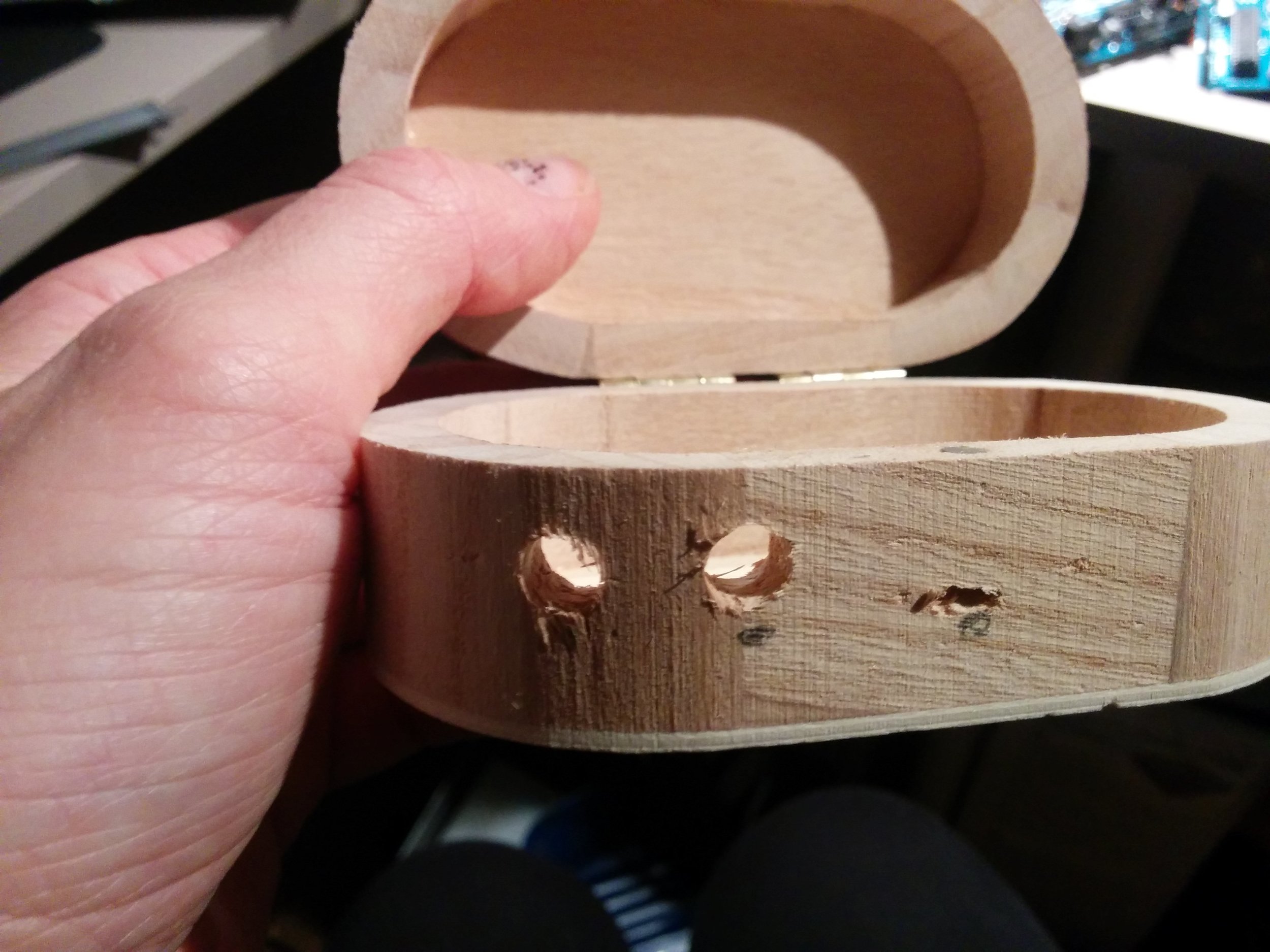
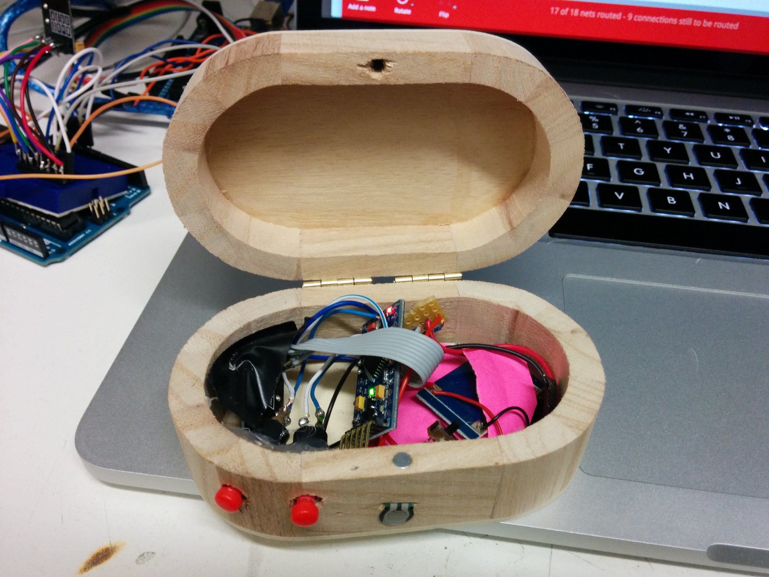
Creating the Filter Box
The box required 2 more holes drilling to match the size of the valve fitting, these then had to be glued into place to secure. A small slit had to be drilled and filed to allow for the FSR to pass through.
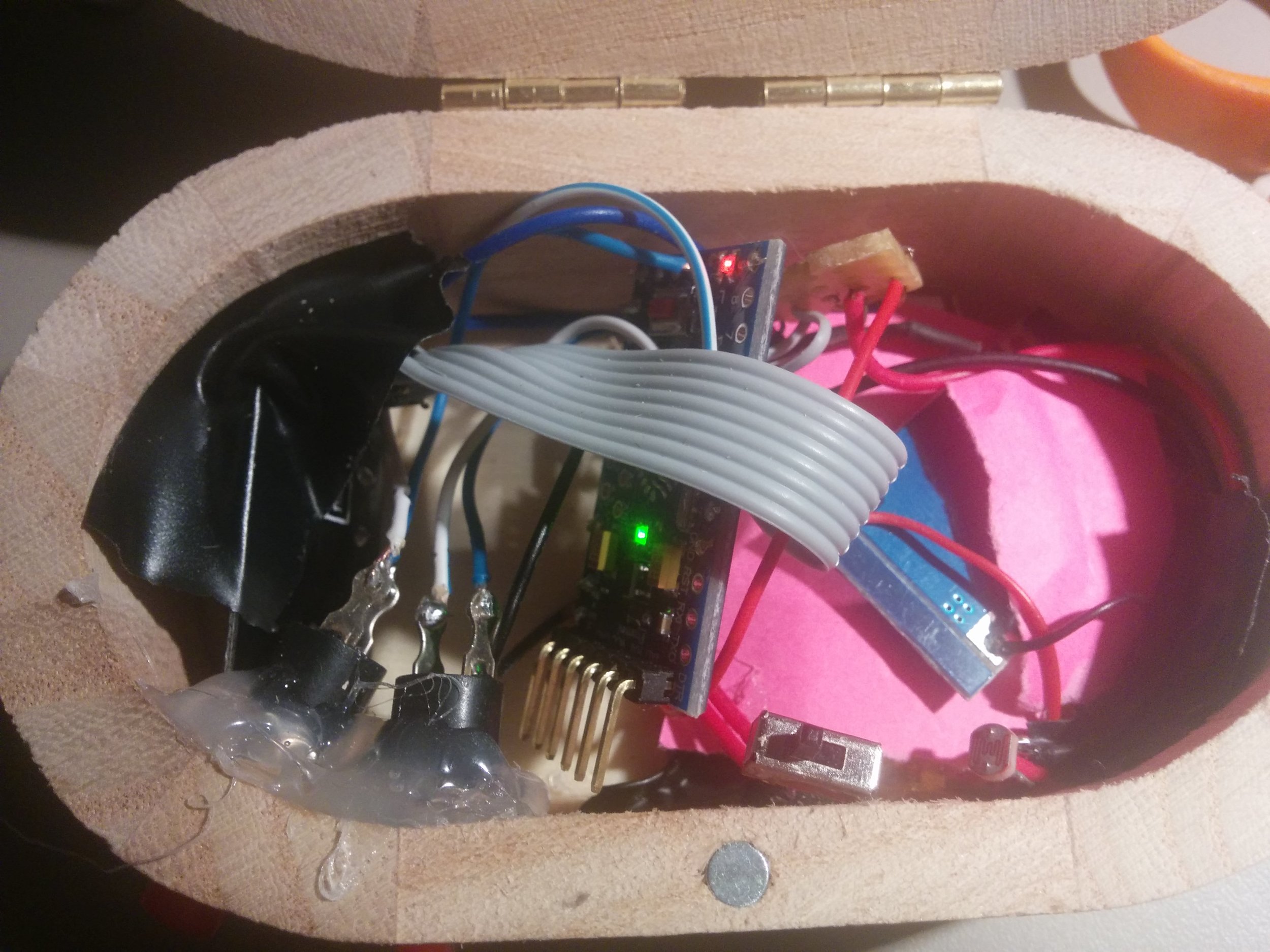
Electrical tape and paper was used to ensure that none of the vital circuitry was touching each other as the box is quite a small space for all the components needed. The Filter Box was then ready for some testing!
The Pressure Box
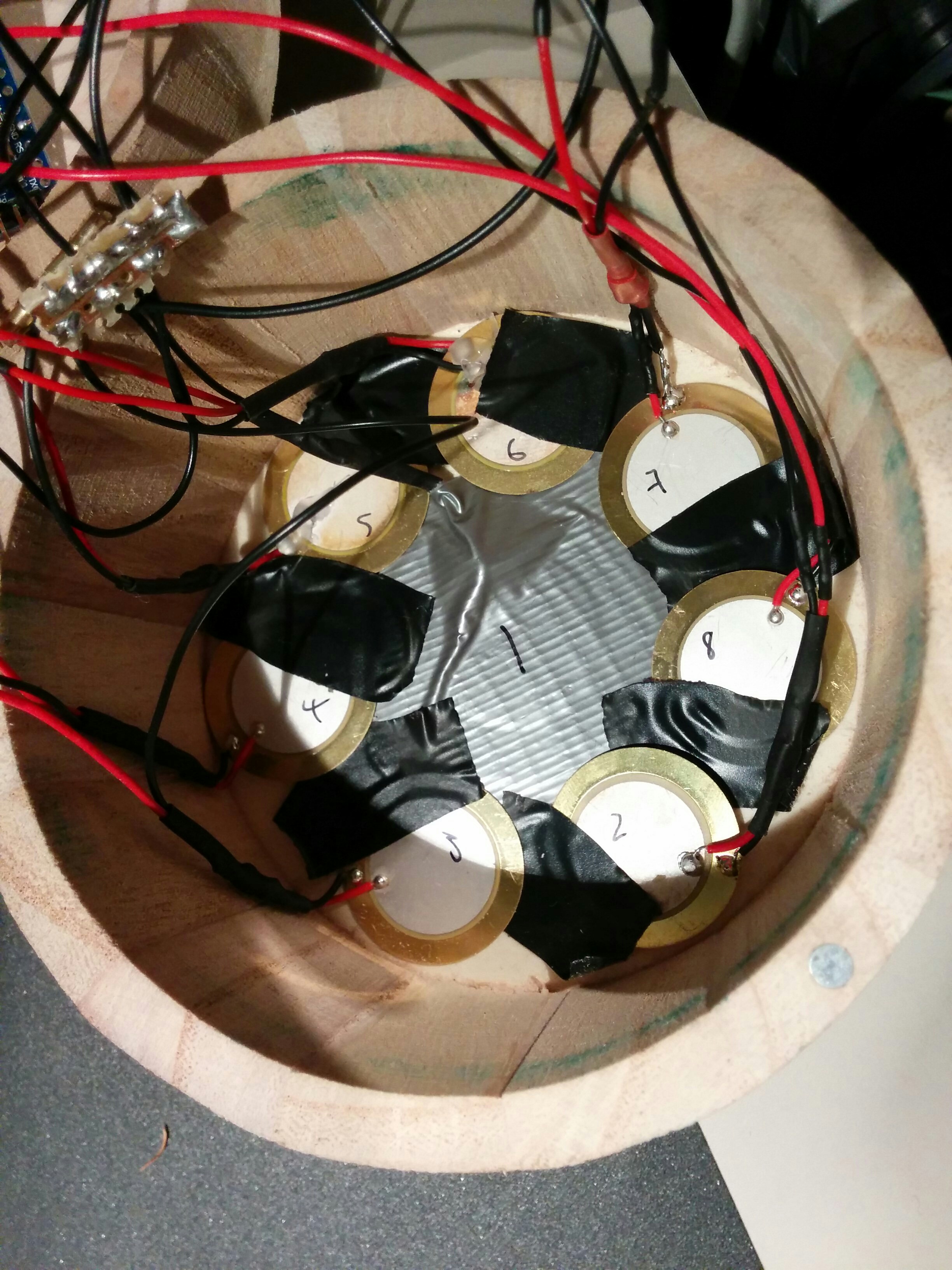
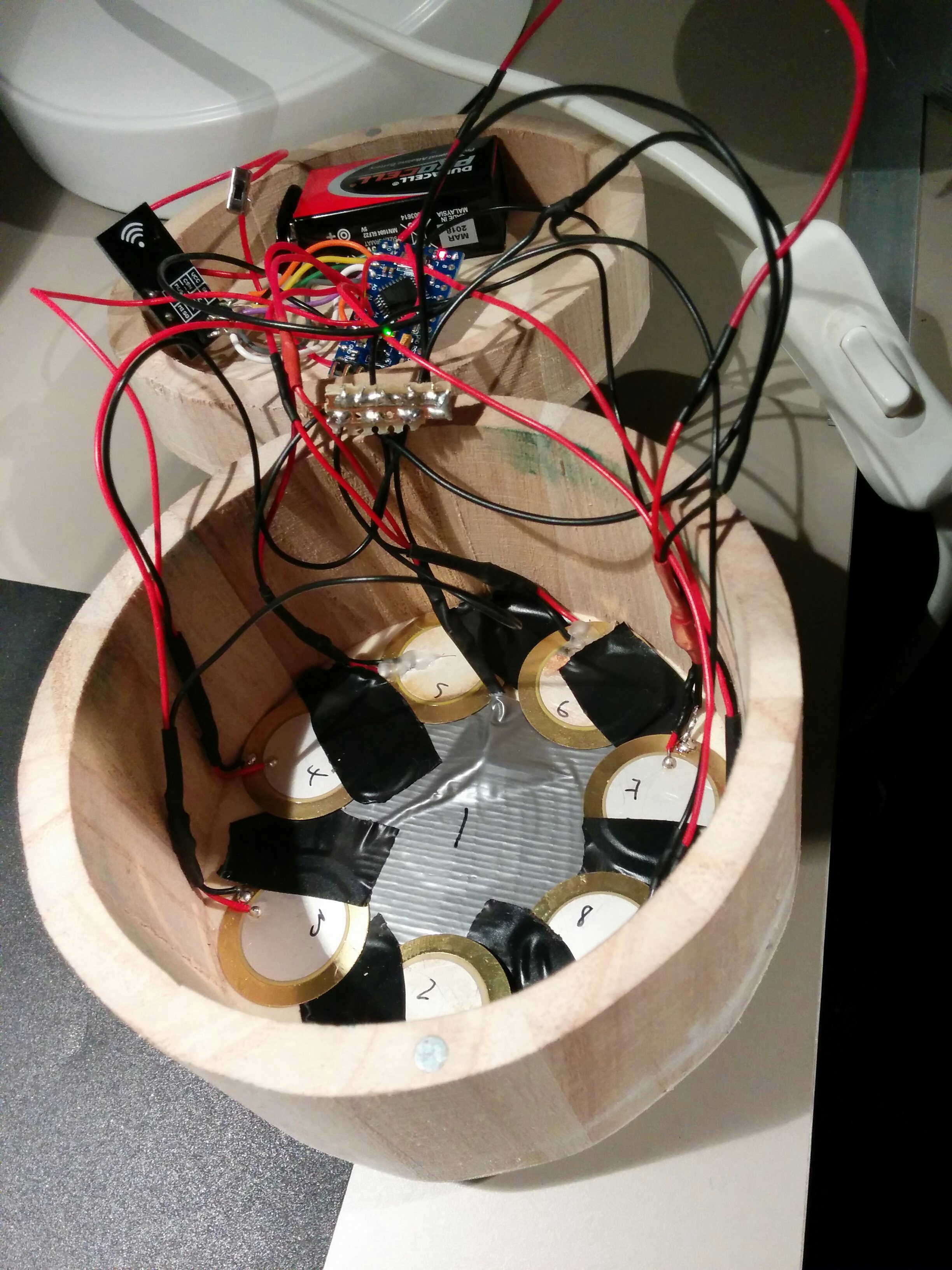
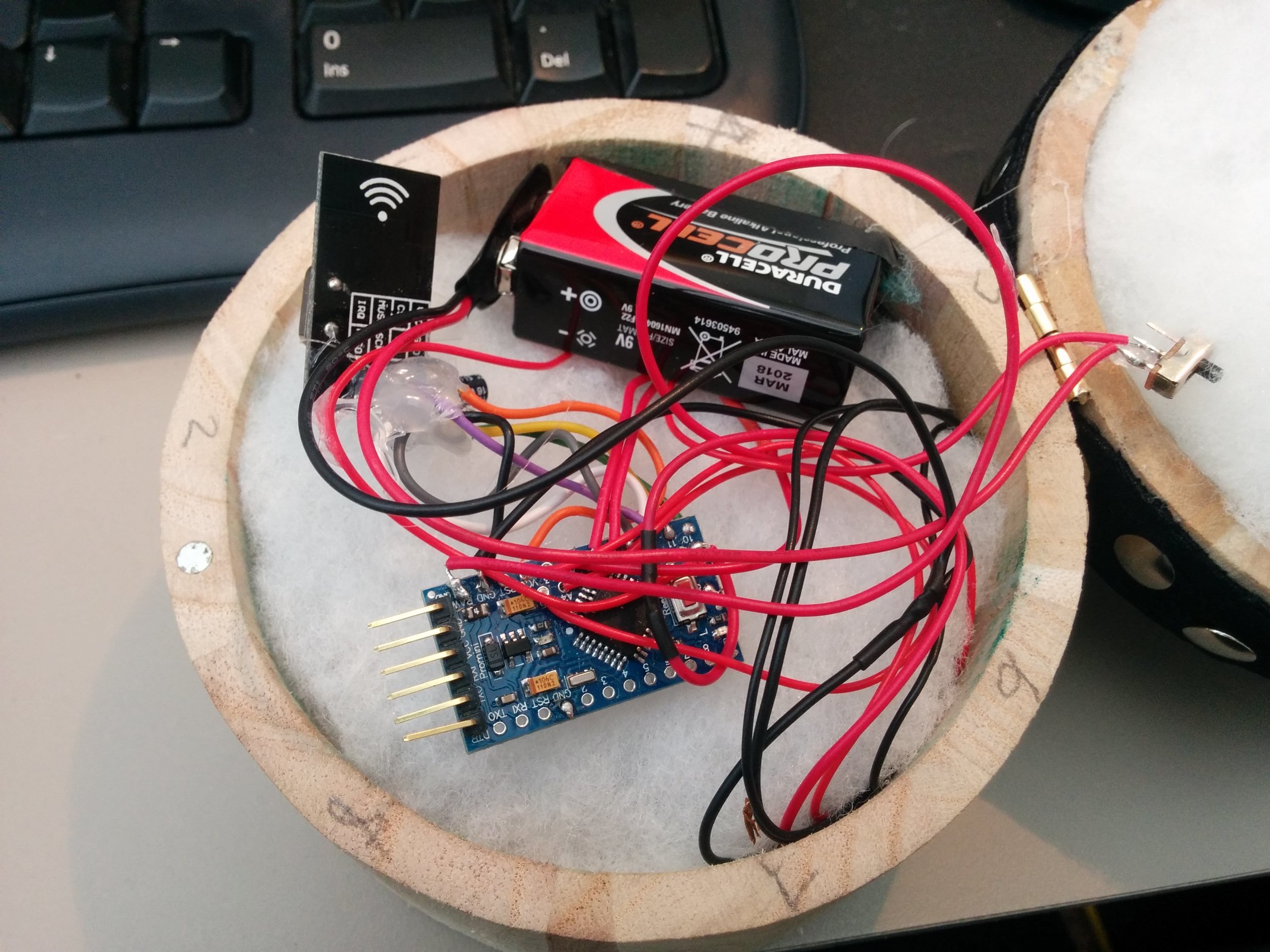
We decided that the bigger rounder box would suit the Pressure Box and so we went about designing the gubbins that would make it work. At the moment whilst awaiting deliveries for lithium rechargeable batteries we have stuck with the good old 9v square battery which differs from what is seen in the circuit diagram. The Pressure box uses the same Arduino and radio combo as the Filter Box but we are will be using 8 piezos as analogue inputs instead, 1 large for the centre and 7 smaller for the outer ring. Piezos are very cheap and very sensitive so should give us good feedback as to where on the top of the box is being pressed.
The Circuit:

Here is a more simplified view of how each piezo is wired in:

A note about the circuit: The software used to draw up the circuit didn't have the exact same Arduino board as we are using so the green section to the left of the Arduino board is simulating the analogue inputs that are in different positions on the Arduino. The picture below shows more clearly the holes for the analogue inputs (A0-A7) A4 and A5 are the holes above A2 and A3.
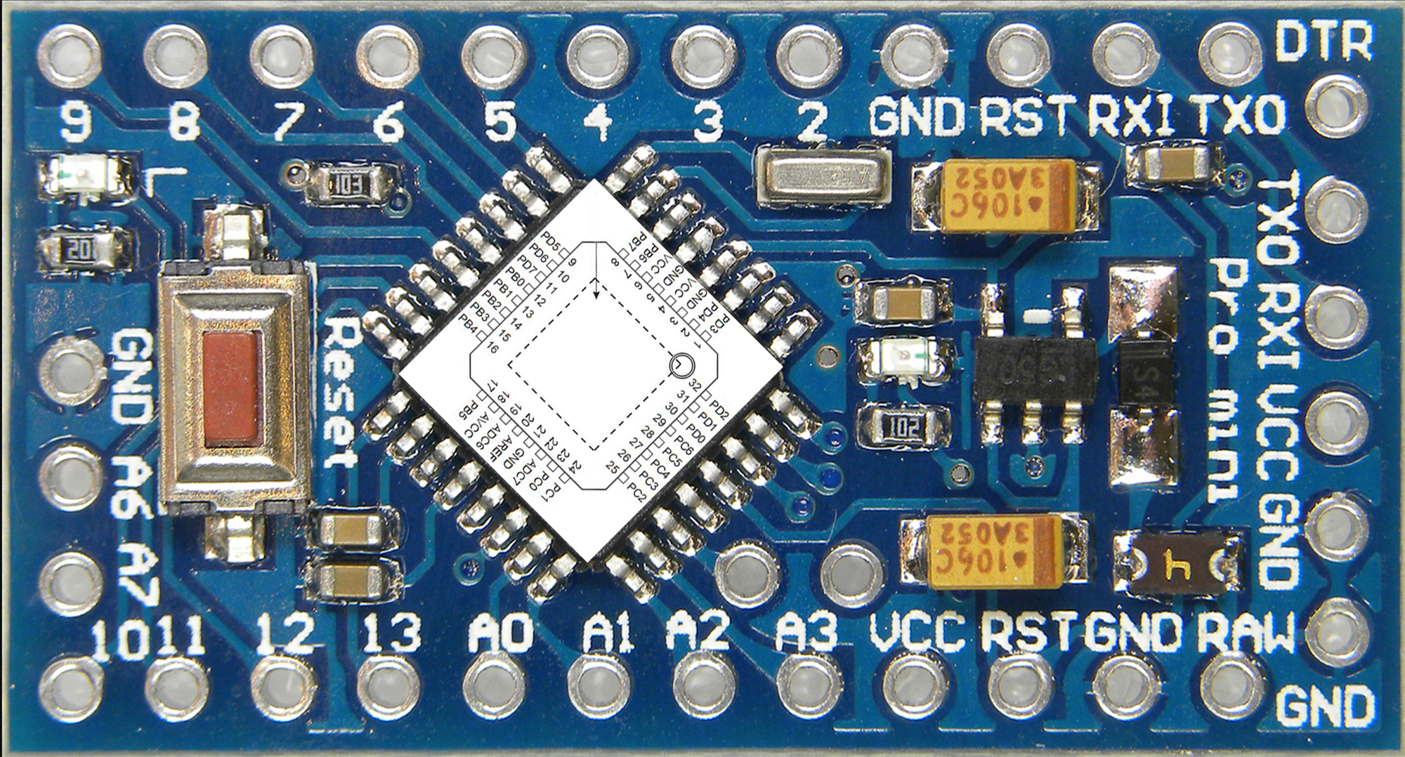
Image from http://www.dominicdube.com/wp-content/uploads/ArduinoProMini000b.jpg
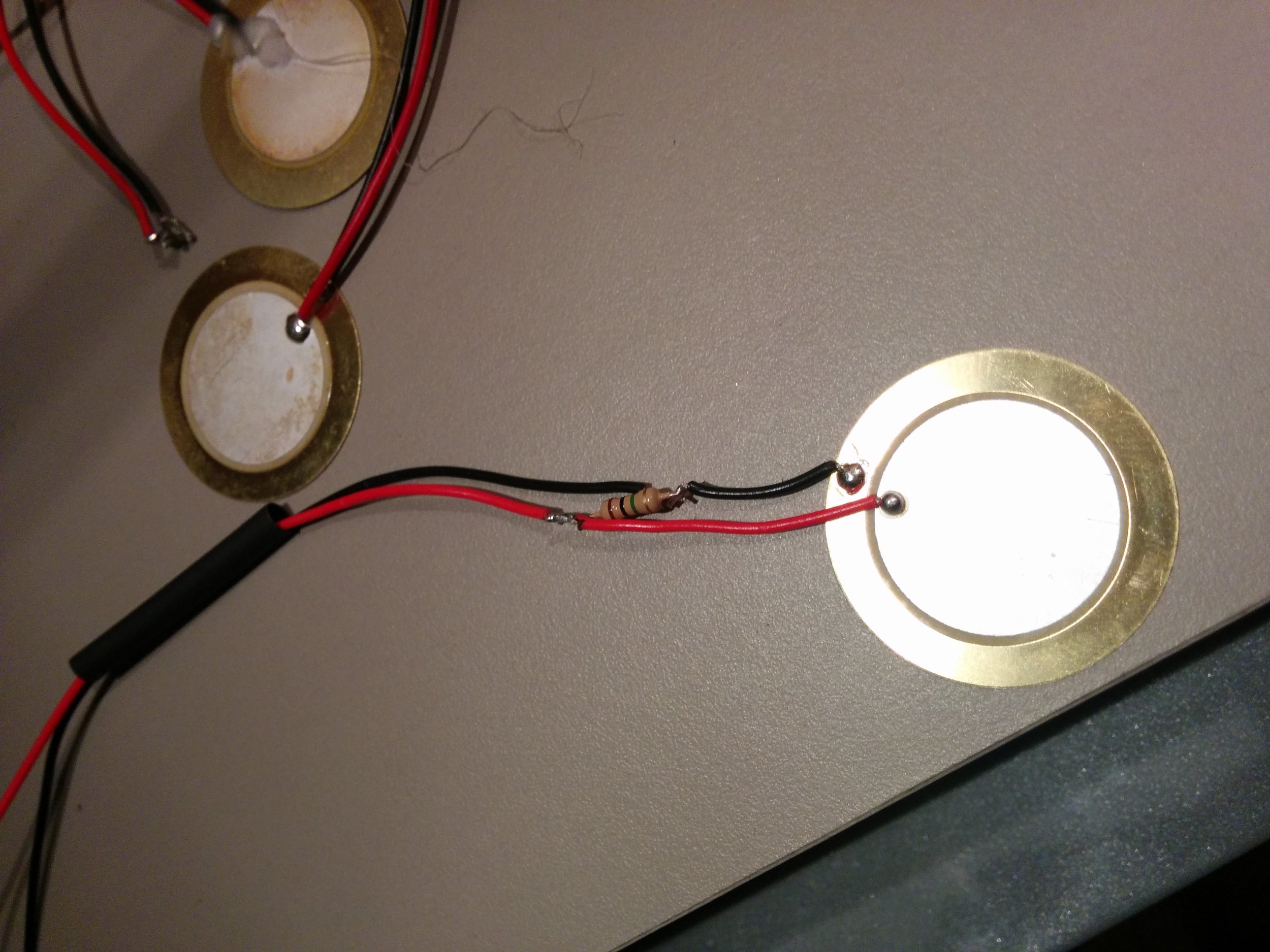
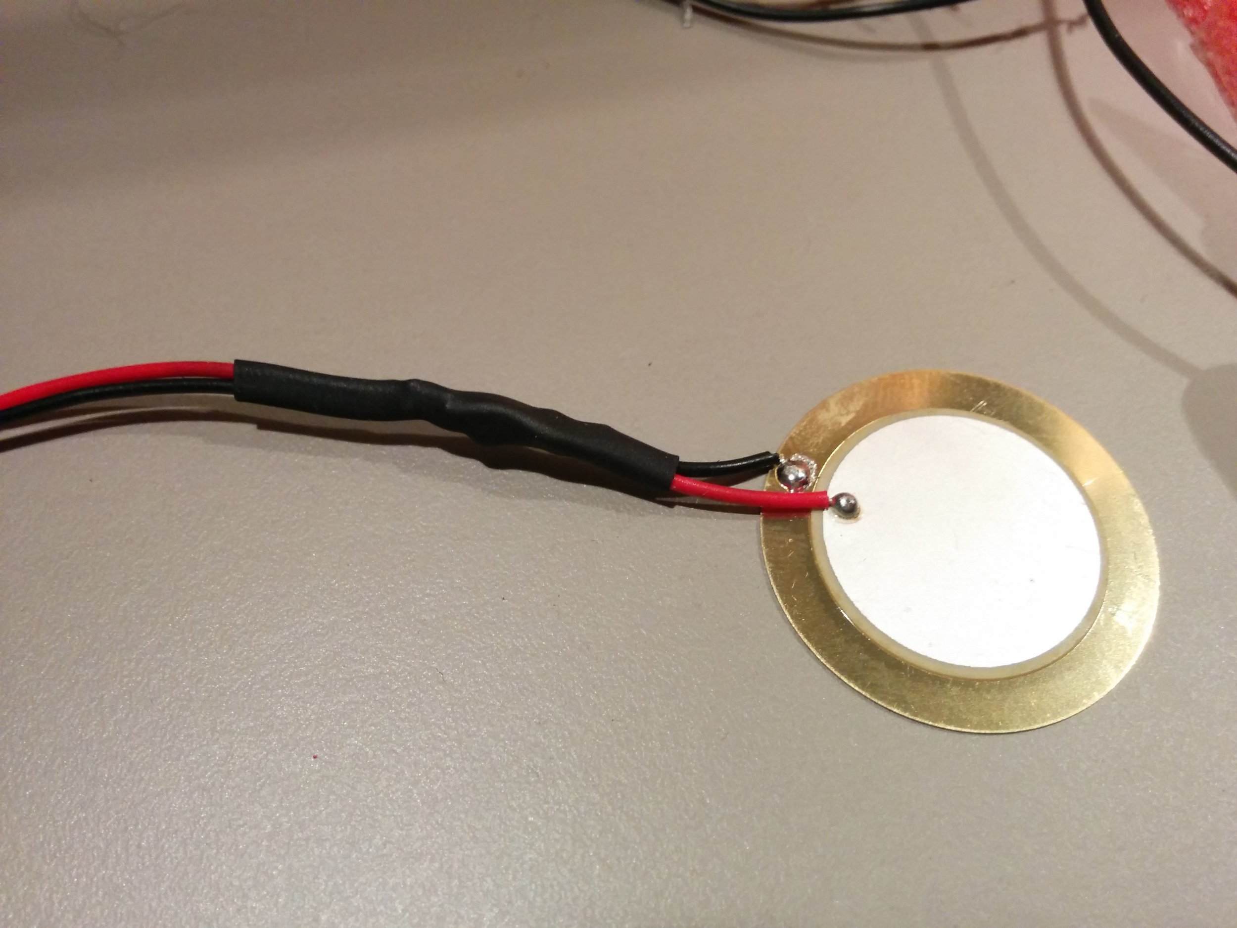
Each of the piezos had to be prepped as they require a 1 MOhm resistor running between their 2 wires as seen in the circuit diagram. The resistor was installed at near the disc of the piezo and some heat shrink was used to seal everything in.
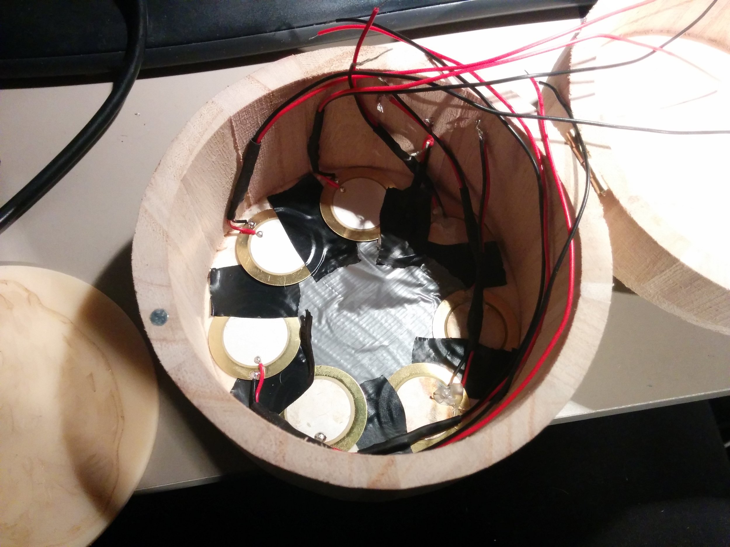
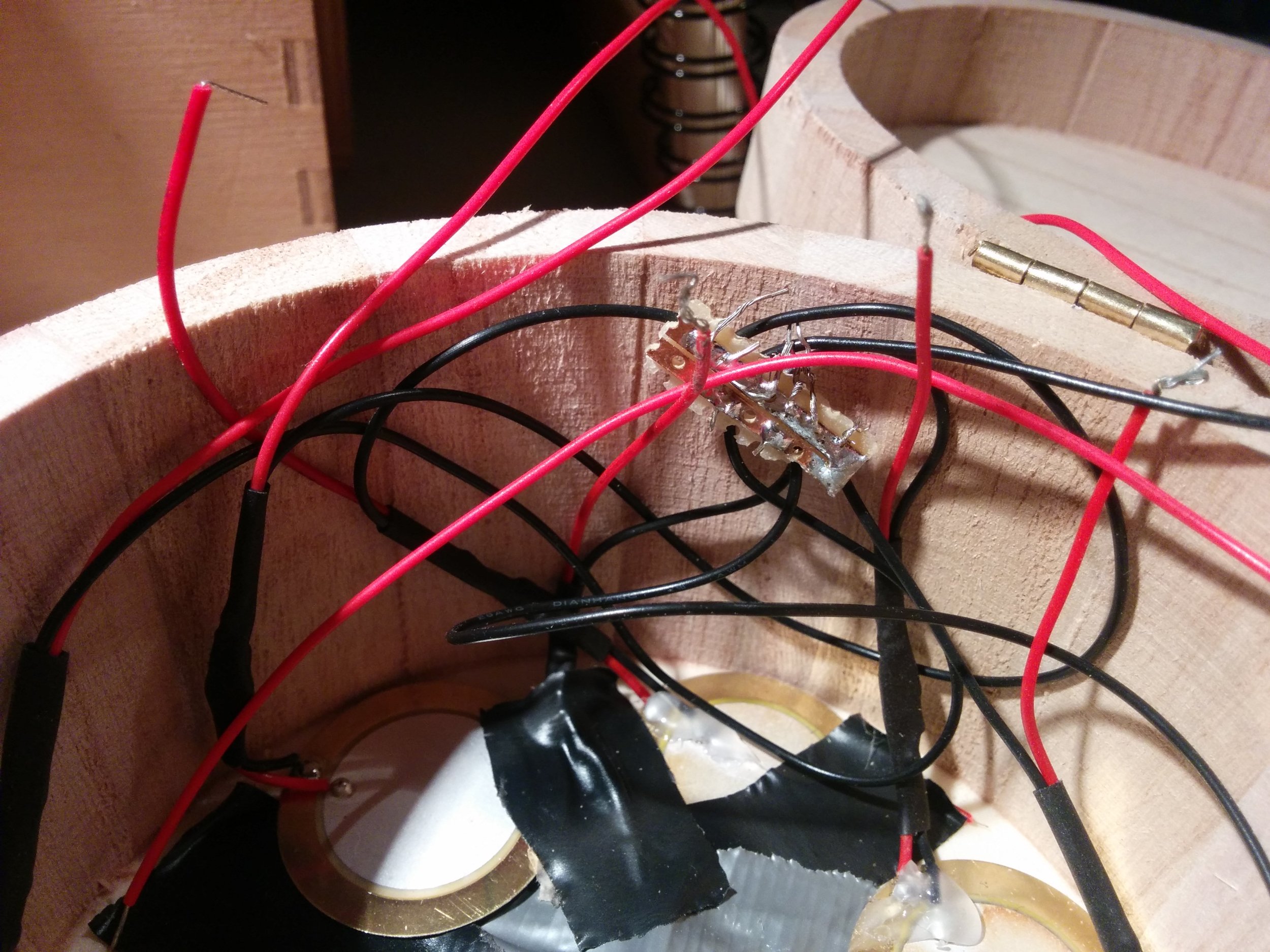
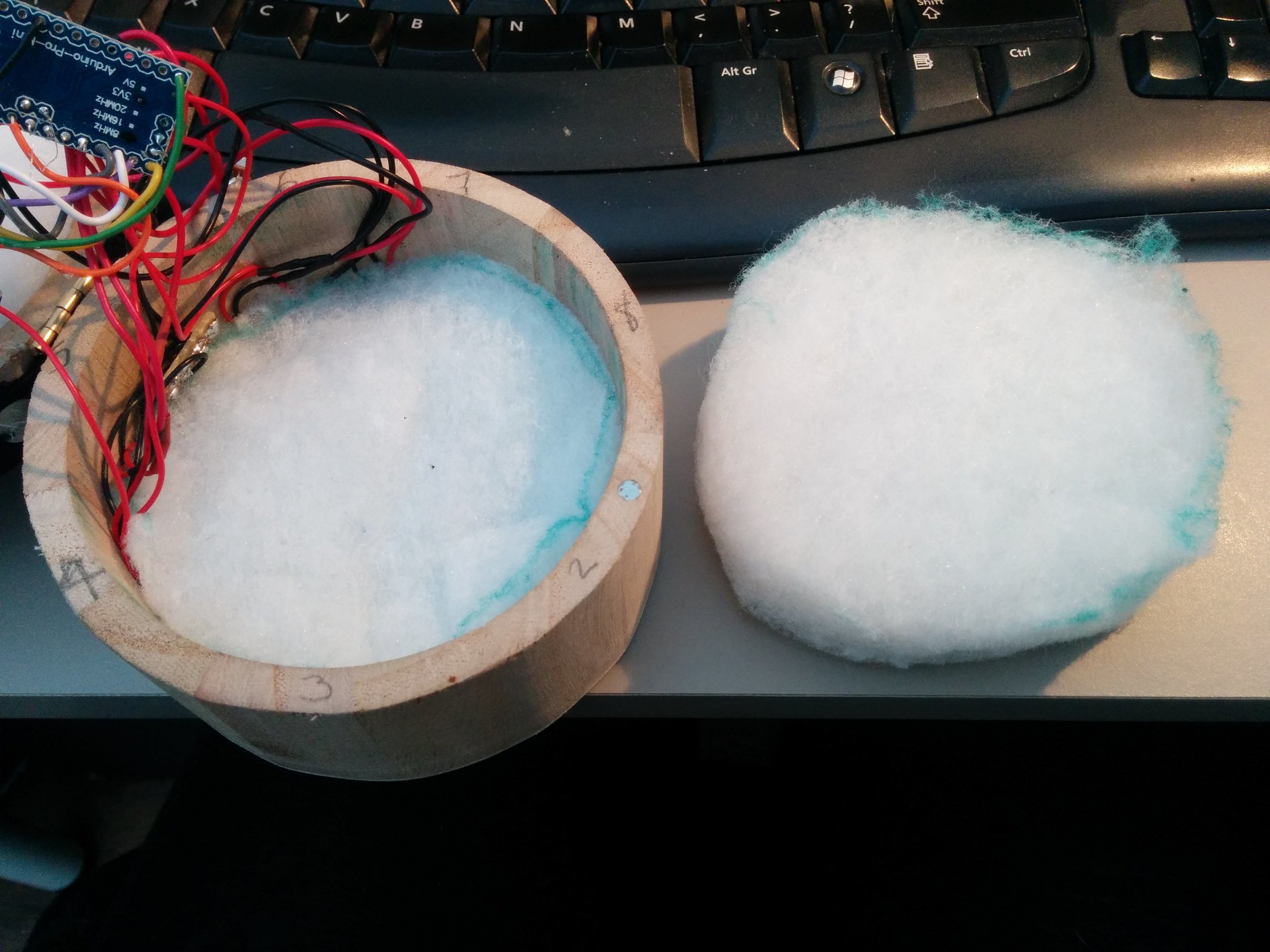
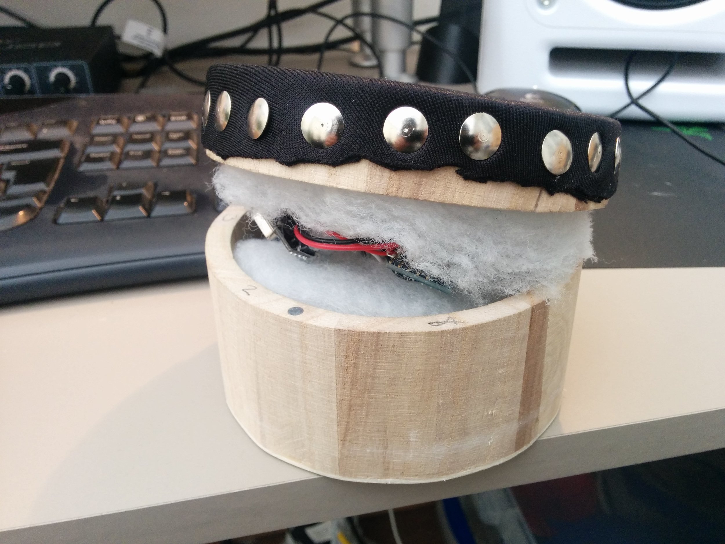
The piezos were then arranged around the bottom of the box with electrical tape to stop them touching. Two layers of thick but airy foam wadding were used to provide the bouncy resistance needed. The components were stashed between the two layers. Once the correct battery has arrived these components should sit nicely over the middle piezo.
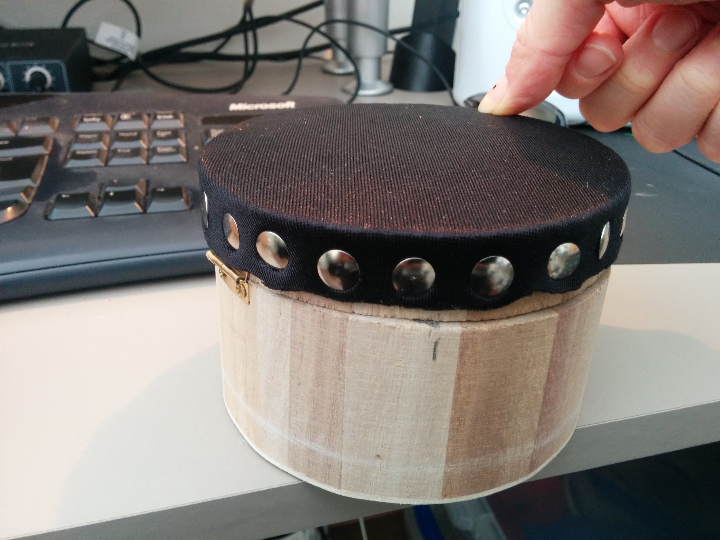
Attention then turned to the lid. We decided it would be best to cut out a hole in the lid thus having a ring of wood on which to attach the skin (tambourine style) and then pin it on the edges with thumb tacks. This would also allow us to put clasps on the side of the lid to attach to the box so as to provide access to the components if needed without removing the skin.
We took to the CNC router to nicely remove the inner lid before adding the skin made from a thick piece of lycra like material folded double.
Testing will be done with these prototypes to see what the next steps are........