Part 2 - RGB LEDs and PWM
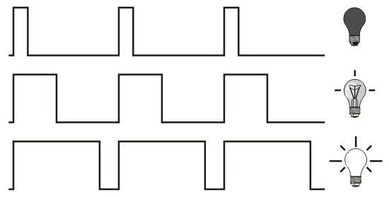
LEDs are digital components, i.e. they are on or off. We can't fade them properly by controlling the amount of power going to them like you would an incandescent light bulb, but what we can do is turn them on and off really fast and make them appear to be dimmer. To do this we use PWM.
PWM stands for Pulse Width Modulation and enables us to essentially turn the output from the digital pin on and off really fast. We can control the 'duty cycle' with a number between 0 (fully off) and 255 (fully on) and it can be used to control LED fading or for signal applications like controlling servo motors. You may have noticed that some of the pins on your Arduino have a wiggly line next to them (otherwise known as a 'tilde'), in the Leonardo's case 3, 5, 6, 9, 10, 11 and 13. These pins can do hardware PWM and are good for us to use for dimming our LED, handy as we have already used these pins for our circuit...
PWM in action, though using an incandescent light bulb graphic instead of an LED doesn't make sense...
For this exercise we are going to use an analog input pin connected to a potentiometer, or 'pot'. This means we are measuring real voltage values between 0 and 5V rather than just looking for HIGH (5V) or LOW (0V) like we would on a digital pin input. The Arduino's analog to digital converter will turn this voltage measurement into an integer between 0 and 1023. We can then use the function 'map()' to scale our input to say 0 - 255 to control our LED with PWM. Build the circuit and follow the instructions below.
The circuit:
- Open the 'AnalogInOutSerial' sketch from the 'File > Examples > 03.Analog' menu in the Arduino IDE
- Upload the sketch and you should be able to fade the blue LED, open the 'Serial Monitor' with the icon in the top right of your Arduino IDE window, you should see the values changing. Serial.print is great for debugging our code! Serial.println will put a carriage return at the end of the print.
- Look at the reference page for the 'map()' function and see how it is used in the sketch
- Also, have a look at the 'constrain()' function, it may be useful in the next exercise...
- Write a sketch that uses the incoming pot value to first fade up the red LED, then the green LED, then the blue so that we finally have white. We are essentially splitting the input into 3 bands which each control an LED.
+ Hint 1
Make sure you have declared all the LED pins, then you will need a variable to hold each LED value
+ Hint 2
Use 'constrain()' to split the incoming 0 - 1023 value into 3 bands of: 0-341, 342-682, 683-1023 and store it in our LED value variables
+ Hint 3
Use 'map()' to map our new LED values to 0-255 for controlling LEDs and use 'analogWrite()' to send them out
+ The solution
Here's one way of doing it, there's always more than one way! Copy and paste into you Arduino IDE, it may be easier to read.
/*
 *   Control an RGB LED with a potentiometer
 *  We want to fade up each LED in turn
 *  so will be splitting the incoming
 *  pot value into 3 and remapping it
 *
 *  Luke Woodbury 10 January 2017
 *  dotLib.org
 *
 */

//these are constants, they won't change
const int potPin = A0;  //pin for the potentiometer
const int redPin = 10;  //the LED pins
const int grnPin = 6;
const int bluPin = 9;

//these are variables, we are going to use them to
//hold changing values
int potVal = 0;
int redVal = 0;
int grnVal = 0;
int bluVal = 0;


void setup() {
  // declare the LED pins OUTPUTs
  pinMode(redPin, OUTPUT);
  pinMode(grnPin, OUTPUT);
  pinMode(bluPin, OUTPUT);
}

void loop() {
  // read the value from the sensor:
  potVal = analogRead(potPin);
  //now constrain the 3 bands of the 0-1023 input
  //and store them in our variables
  redVal = constrain(potVal, 0, 341);
  grnVal = constrain(potVal, 342, 682);
  bluVal = constrain(potVal, 683, 1023);

  //remap the stored values for LED PWM fading
  redVal = map(redVal, 0, 341, 0, 255);
  grnVal = map(grnVal, 342, 682, 0, 255);
  bluVal = map(bluVal, 683, 1023, 0, 255);

  //write values to LED pins as PWM
  analogWrite(redPin, redVal);
  analogWrite(grnPin, grnVal);
  analogWrite(bluPin, bluVal);

  // wait 2 milliseconds before the next loop
  // for the analog-to-digital converter to settle
  // after the last reading:
  delay(2);
}

